Analysis of compliant matrix for reinforced flexure hinge
Jiabin Pan*, Yanan Zhang*, Zhongtao Fu*, Linyong Shen, Peiwu Yang
- *Equal Contribution
Abstract
Compared with the traditional parallel mechanism, compliant parallel mechanism (CPM) has significant advantages in high accuracy and good stability, which makes it widely applied in precision engineering. However, most of the current research only focuses on motion accuracy, due to the lack of consideration of large load problems, the application of CPM is greatly limited. To this end, a flexible support module (FSM), as well as its stiffness model, was presented in this paper. Combined with finite element method (FEM) of FSM, structure size optimization was also completed, successfully solved the problems of stress concentration and load of FSM in engineering application. Moreover, a dual vision-based measurement method was introduced, to verify the stiffness model and analyze the repetitive error of FSM. From this result, the prototype enabled 5 mm and 0.007 rad of working area with average error of 0.3192 mm and -0.0036 rad. The repeatable error is within 7%, and will decreased to 4% with internal stress realeased in 5~15min.
Design and analysis of flexure hinge
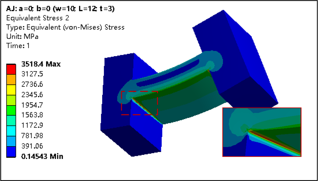
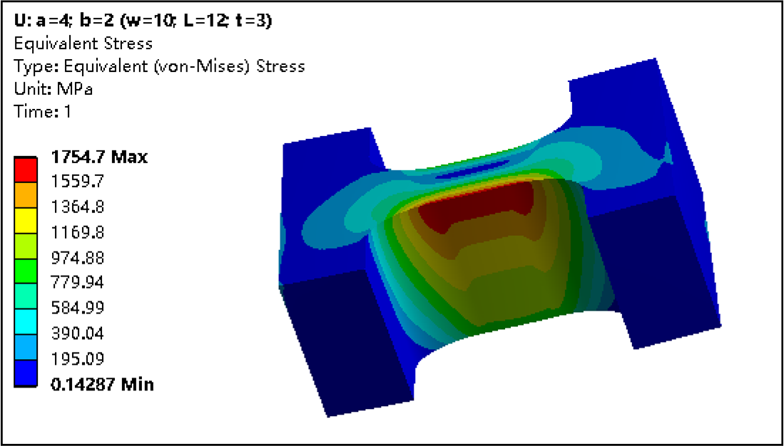
The traditional straight beam flexure hinge can meet the needs of bending deformation to a certain extent, but for some applications with large load, the straight beam flexure hinge often causes stress concentration, and most of these concentrated stresses are distributed at both ends of the straight beam flexure hinge, as shown in Fig.1 (a), which is easy to cause the fatigue fracture of the flexure hinge, In order to solve the stress concentration problem of flexure hinges, scholars usually tend to design flexure hinges with semicircle arc interface. Semicircle arc can greatly increase the load capacity of flexure hinges, but at the same time it can reduce the bending deformation capacity of flexure hinges. Therefore, this paper synthesizes the advantages and disadvantages of the above hinges, and designs a flexure hinge with the structure shown in Fig.1 (b).
The corresponding profile is shown in Fig.2
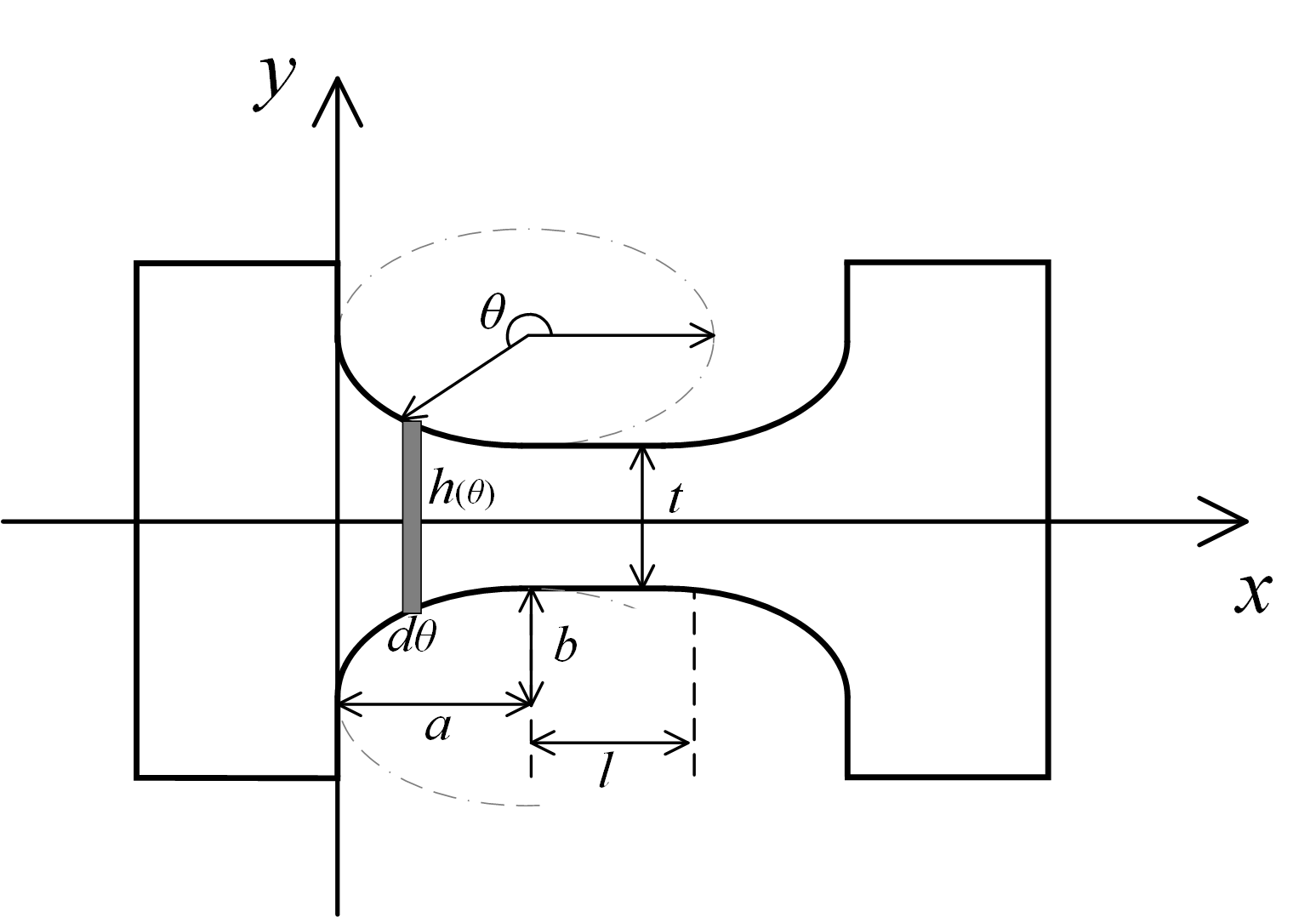
Its edge curve can be formulated as:
$ \begin{align*} y(x)=\begin{cases} \sqrt{b^2-\frac{b^2}{a^2}(x-a)^2}-b-\frac{t}{2} &(0 < x < a) \\ -t/2 &(a \le x < a+l) \\ \sqrt{b^2-\frac{b^2}{a^2}(x-a-l)^2}-b-\frac{t}{2} &(a+l \le x < 2a+l) \end{cases} \end{align*}$
In order to simplify the integral calculation of flexibility, the independent variables of ellipse formula can be parameterized, then the contour equation can be converted as:
$ \begin{align*} y(\theta)=\begin{cases} b\cos\theta-b-\frac{t}{2} &(x=a\sin\theta+a,-\frac{\pi}{2}<\theta < 0) \\ -t/2 &(a \le x < a+l) \\ b\cos\theta-b-\frac{t}{2} &(x=a\sin\theta+a+l,0 \le \theta < \frac{\pi}{2}) \end{cases} \end{align*}$
Compliance equation of RFH
The deformation of the compliant mechanism in one direction is usually determined by multiple forces and moments, which can be calculated by the deflection guide by the Castigliano theorem. The strain energy of the material under the mixed force is composed of bending, shearing, axial strain and torsion, its total strain energy expression is as follows:
$\begin{align*} U=U_{bending}+U_{shearing}+U_{axial}+U_{torsion} \end{align*}$
with
$\begin{align*} U_{bending}=U_{bending,\space y}+U_{bending, \space z}=\int_L{\frac{M_y'^2}{2EI_y}}dx+\int_L{\frac{M_z'^2}{2EI_z}}dx \end{align*}$
$\begin{align*} U_{shearing}=U_{shearing,\space y}+U_{shearing, \space z}=\int_L{\frac{k F_y'^2}{2GA}}dx+\int_L{\frac{k F_z'^2}{2GA}}dx \end{align*}$
$\begin{align*} U_{axial}=U_{axial,\space x}=\int_L{\frac{ N_x'^2}{2EA}}dx \end{align*}$
$\begin{align*} U_{torsion}=U_{torsion,\space x}=\int_L{\frac{ M_x'^2}{2GJ}}dx \end{align*}$
where $M'$ and $F'$ represent bending moment and shear force inside hinge respectively, and $N'$ represents normal stress. According to Castigliano's second theorem, the deflection of angle and displacement of a flexible body at point $P$ can be obtained by deriving the strain energy from the external moment $M$ and force $F$,
$\begin{align*} \alpha_{i} = \frac{\partial U}{\partial M_i} , \Delta_i = \frac{\partial U}{\partial F_i} \end{align*}$
1. Angular compliance about the $z$ axis
The angular displacement in $z$axis direction is mainly caused by the internal bending moment, $M_z'$. By deriving the bending strain energy $U_{bending}$ from the bending moment $M_z'$, the expression of $z$ axis angular displacement with respect to the bending moment $M_z$ can be obtained :
$\begin{align*} \alpha_z=\int_{0}^{2a+l}{\frac{M_z'}{E \cdot I_z(x)}}dx=\int_{0}^{2a+l}{\frac{M_z'}{E \cdot [w \cdot h^3(x)/12]}}dx \end{align}$
The internal bending moment of the material can be divided into two parts: the bending moment $M_z$ directly applied to the end of the hinge, and the equivalent bending moment $M_z^{e}$ caused by the force $F_y$.
For the first kind of angular deformation displacement, $M_z'=M_z$, the relation coefficient is obtained by substituting the above formula. When Eq.(23) is integrated from $0$ -> $a$ and $a+l$ -> $2a+l$ , the integration of $\theta$ will be carried out from $-\pi/2$ -> $0$ and $0$ -> $\pi/2$. Substituting the flexure hinge thickness expression $h(x)=-2y(x)$ into Eq.(23), we can obtain the compliance equation of angular displacement with respect to moment $M_Z$,
$ \begin{align*} \frac{\alpha_z}{M_z} &=-\frac{3}{2Ew}\int_{0}^{2a+l}{\frac{1}{y^3(x)}}dx \\ &=-\frac{3}{2Ew}[\int_{-\frac{\pi}{2}}^{\frac{\pi}{2}}{\frac{a\cos\theta}{(b\cos\theta-b-\frac{t}{2})^3}}d\theta+\int_a^{a+l}{(-\frac{2}{t})^3}dx] \\ &=\frac{12l}{Ewt^3}-\frac{3a}{Ew}\int_{0}^{\frac{\pi}{2}}{\frac{\cos\theta}{(b\cos\theta-b-\frac{t}{2})^3}}d\theta \\ &=\frac{12l}{Ewt^3}-\frac{3a}{Ew}\cdot N_1 \end{align*}$
where, the complex integral term, $N_1$, can be obtained by the algebra software, Mathematica,
$ \begin{align*} N_1&=\int_0^{\frac{\pi}{2}}{\frac{\cos\theta}{(b\cos\theta-b-\frac{t}{2})^3}}d\theta \\ &=-8[\frac{t^2+4bt+6b^2}{t^2(4b+t)^2(2b+t)}+\frac{6b(2b+t)\arctan{\sqrt{4b/t+1}}}{t^{5/2}(4b+t)^{5/2}}] \end{align*}$
For the compliance of angle displacement $\alpha_z$ on the end force $F_y$, the force is usually converted into the equivalent moment first, that is:
$\begin{align*} M_z^e=\begin{cases} (a\sin\theta+a)\cdot F_y & (-\frac{\pi}{2}<\theta< 0)\\ x\cdot F_y & (a \le x< a+l)\\ (a\sin\theta+a+l)\cdot F_y & (0 \le \theta < \frac{\pi}{2}) \end{cases} \end{align*}$
Substituting it into Eq.(23), we can get:
$\begin{align*} \frac{\alpha_z}{F_y}=-\frac{3}{2Ew}\cdot (\int_{-\pi/2}^{0}{\frac{(a\sin\theta+a)a\cos\theta}{(b\cos\theta-b-\frac{t}{2})^3}}d\theta+\int_a^{a+l}{\frac{x}{(-t/2)^3}}dx+\int_0^{\pi/2}{\frac{(a\sin\theta+a+l)a\cos\theta}{(b\cos\theta-b-\frac{t}{2})^3}}d\theta) \end{align*}$
which can be reduced to:
$\begin{align*} \frac{\alpha_z}{F_y}=\frac{6l(2a+l)}{Ewt^3}-\frac{3a(2a+l)}{2Ew}N_1 \end{align*}$
The definition of the complex integral term $N_1$ is given by Eq.(25). Comparing the results of Eq.(24) and Eq.(28), we propose the first inference:
$\bold{Conclusion \ 1:}$
2. Angular compliance about the $y$ axis
For the calculation of the flexural flexibility relation of the $y$ axis, it has the same method as above. By deriving the strain energy $U_{bending$ from the bending moment $M_y'$, the integral expression of the angle $\alpha_y$ with respect to the bending moment $M_y$ is obtained,
$\begin{align*} \alpha_y=\int_{0}^{2a+l}{\frac{M_y'}{E \cdot I_y(x)}}dx=\int_{0}^{2a+l}{\frac{M_y'}{E \cdot [w^3 \cdot h(x)/12]}}dx \end{align*}$
By substituting $M_y' = M_y$ into the above formula and simplifying, the compliance equation of bending moment about $y$ axis, is expressed as:
$\begin{align*} \frac{\alpha_y}{M_y}=\frac{12l}{Ew^3t}-\frac{12a}{Ew^3}\cdot N_2 \end{align*}$
where
$\begin{align*} N_2=\int_0^{\pi/2}{\frac{\cos\theta}{b\cos\theta-b-\frac{t}{2}}}d\theta=\frac{\pi}{2b}-\frac{2(2b+t)}{b\sqrt{t}\sqrt{4b+t}}\arctan\sqrt{\frac{4b}{t}+1} \end{align*}$
The angular displacement in the $y$ axis direction is also affected by the force $F_z$. The compliance equation of $\alpha_y$ with respect to $F_z$ can also be derived via the process of Eq.(26)-(28):
$\begin{align*} \frac{\alpha_y}{F_z}=\frac{6l(2a+l)}{Ew^3t}-\frac{6a(2a+l)}{Ew^3}\cdot N_2 \end{align*}$
3. Angular compliance about the $x$ axis
4. Linear compliance about the $z$ axis
The linear deformation displacement on the $z$ axis mainly includes two aspects: one is displacement caused by bending deformation, the other is related to shear deformation, and their corresponding strain energy are $U_{bending}$ and $U_{shearing}$ respectively, where $U_{bending}$ is caused by the combined action of bending moment $M_y$ and force $F_y$ (equivalent bending moment $M_y^e$). When the flexure hinge just has small deformation, the deformation, $\Delta_z$, caused by bending moment $M_y$ can be obtained by integrating the angle displacement $\alpha_y^M(x_t)$, expressed as:
$\begin{align*} \Delta_z=\int_L{\alpha_y^M(x_t)}dx \end{align*}$
where $\alpha_y^M(x_t)$ is the displacement of flexure hinge at $x=x_t$, defined as:
$\begin{align*} \alpha_y^M(x_t)=\int_{0}^{2a+l}{\frac{M_y}{E \cdot [w^3 \cdot h(x)/12]}}dx=-\frac{6M_y}{Ew^3}\int_{0}^{x_t}{\frac{1}{y(x)}}dx \end{align*}$
Substituting Eq.(34) into (33), the linear compliance of bending moment $M_y$ can be expressed as:
$\begin{align*} \frac{\Delta_z}{M_y}=-\frac{6}{Ew^3}\int_0^{2a+l}dx_t\int_0^{x_t}{\frac{1}{y(x)}}dx \end{align*}$
Define the integral function $f(x_t)=\int_0^{x_t}{\frac{1}{y(x)}}dx$, which is a three segment function. Parameterize the independent variables of first and third segment function,
$\begin{align*} f_1(\theta_t)=&\int_{-\pi/2}^{\theta_t}{\frac{a\cos\theta}{b\cos\theta-b-t/2}}d\theta &&(x_t=a\sin\theta_t+a, 0< x_t< a) \\ f_2(x_t)=&f_1(a)+\int_a^{x_t}{\frac{1}{-t/2}}dx &&(a< x_t< a+l) \\f_3(\theta_t)=&f_2(a+l)+\int_0^{\theta_t}{\frac{a\cos\theta}{b\cos\theta-b-t/2}}d\theta &&(x_t=asin\theta_t+a+l, a+l< x_t< 2a+l) \end{align*}$
which shows that Eq.(35) needs to be divided into three parts for integration, that is $0$ ~ $a$, $a$ ~ $a+l$, $a+l$ ~ $2a+l$. In the first and third integral segments, the variable $x_t$ is parameterized as $\theta_t$ for integration, and its corresponding integral region will change to $-\pi/2$ ~ $0$ and $0$ ~ $\pi/2$, and the Eq.(35) will be converted into
$\begin{align*} \frac{\Delta_z}{M_y}=-\frac{6}{Ew^3}(\int_{-\pi/2}^{0}a\cos\theta_t f_1(\theta_t) d\theta_t+\int_a^{a+l}f_2(x_t)dx_t+\int_0^{\pi/2}{a\cos\theta_t f_3(\theta_t)d\theta_t}) \end{align*}$
Simplifying Eq.(36), the linear compliance of bending moment $M_y$ in $z$ axis direction can be obtained
$\begin{align*} \frac{\Delta_z}{M_y}=\frac{6l(2a+l)}{Ew^3t}-\frac{6a(2a+l)}{Ew^3}\cdot N_2 \end{align*}$
Comparing Eq.(37) and Eq.(30), we find that there is a relationship between the compliance factors $\frac{\Delta_z}{M_y}$ and $\frac{\alpha_z}{M_y}$, that is
$\begin{align*} \frac{\Delta_z}{M_y}=\frac1 2(2a+l)\cdot \frac{\alpha_y}{M_y}=\frac L 2\cdot \frac{\alpha_y}{M_y} \end{align*}$
Therefore, we propose a conclusion (the proof of the conclusion is given in published paper):
$\bold{Conclusion \ 2:}$ Under the condition of small deformation, for the flexure hinge with the feature of midline symmetry, there is a relationship between the deformation displacement $\Delta_i^M$ and $\alpha_j^M$ ($i$ and $j$ are mutually perpendicular coordinate axes), which is independent of the shape of the flexure hinge.
As mentioned at the beginning of this section, the linear deformation displacement on the $z$ axis is generated by the strain energy $U_{bending}$ and $U_{shearing}$, and the end force $F_z$ has effect on both of them. Therefore, the deformation displacement caused by the force $F_z$ can be written as:
$\begin{align*} \Delta_z=\Delta_{z,bending}+\Delta_{z,shearing} \end{align*}$
where
$\begin{align*} \Delta_{z,bending}=-\frac{6}{Ew^3}\int_0^{2a+l}dx_t\int_0^{x_t}{\frac{x\cdot F_z}{y(x)}}dx \end{align*}$
Define the function $I(x) = \int_0^{x_t}{\frac{x}{y(x)}}dx$, which can be expressed as
$\begin{align*} I_1(\theta_t)=&\int_{-\pi/2}^{\theta_t}{\frac{a\cos\theta\cdot (a\sin a+a)}{b\cos\theta-b-t/2}}d\theta &&(x_t=a\sin\theta_t+a, 0< x_t< a) \\ I_2(x_t)=&I_1(a)+\int_a^{x_t}{\frac{x}{-t/2}}dx &&(a< x_t< a+l) \\ I_3(\theta_t)=&I_2(a+l)+\int_0^{\theta_t}{\frac{a\cos\theta\cdot(a\sin\theta+a+l)}{b\cos\theta-b-t/2}}d\theta &&(x_t=asin\theta_t+a+l, a+l< x_t< 2a+l) \end{align*}$
substituting into Eq.(40), we can get the linear displacement of bending deformation caused by force $F_z$ in the $z$ axis direction
$\begin{align*} \frac{\Delta_{z,bending}}{F_z}=&\frac{2l}{Ew^3t}(6a^2+6al+l^2)-\frac{12a^2l}{Ew^3}\cdot N_2+\frac{12a^2l}{Ew^3}\cdot N_3 -\frac{12a^3}{Ew^3}\cdot N_4 \end{align*}$
with
$\begin{align*} N_3=&\int_0^{\pi/2}{\frac{\sin\theta \cos\theta}{b\cos\theta-b-\frac{t}{2}}}d\theta= \frac{1}{b}-\frac{2b+t}{2b^2}\ln{(\frac{2b}{t}+1)} \\ N_4=&\int_0^{\pi/2}\frac{\cos^3{\theta}}{b\cos\theta-b-\frac{t}{2}}d\theta=\frac{3\pi+4}{4b}+\frac{(\pi+1)t}{2b^2}+\frac{\pi t^2}{8b^3}-\frac{(2b+t)^3}{2b^3\sqrt{t}\sqrt{4b+t}}\arctan\sqrt{\frac{4b}{t}+1} \end{align*}$
For the shear deformation part $\Delta_{z, shearing}$, it can be deduced by deriving the force $F_z$ from Eq.(19)
$\begin{align*} \Delta_{z,shearing}=\int_L{\frac{kF_z}{GA}}dx=\int_0^{2a+l}{\frac{kF_z}{Gwh(x)}}dx \end{align*}$
where $k$ is a coefficient depending on the shape of the section. In this paper, the flexure hinge is a rectangular section, $k$ can directly be given as following formula:
$\begin{align*} k=\frac{12+11\mu}{10+10\mu} \end{align*}$
where $\mu$ is the Poisson's ratio of the material ($\mu=E/(2G)-1$),
Therefore, Eq.(44) can be deduced as:
$\begin{align*} \frac{\Delta_{z,shearing}}{F_z}=\frac{kl}{Gwt}-\frac{ka}{Gw}\cdot N_2 \end{align*}$
By summing Eq.(41) and Eq.(46), the linear compliance of force $F_z$ can be obtained
$\begin{align*} \frac{\Delta_z}{F_z}=&[\frac{2l}{Ew^3t}(6a^2+6al+l^2)+\frac{kl}{Gwt}]-(\frac{12a^2l}{Ew^3}+\frac{ka}{Gw})\cdot N_2+\frac{12a^2l}{Ew^3}\cdot N_3 -\frac{12a^3}{Ew^3}\cdot N_4 \end{align*}$
5. Linear compliance about the $y$ axis
Like the linear deformation of $z$ axis, the linear deformation of $y$ axis also consists of shear deformation $U_{shearing}$ and bending deformation $U_{bending}$, which are determined by bending moment $M_z$ and force $F_y$. For the first part, this section can be directly obtained by using $\bold{Conclusion \ 2}$
$\begin{align*} \frac{\Delta_y}{M_z}=\frac1 2(2a+l)\cdot \frac{\alpha_z}{M_z}=\frac{6l(2a+l)}{Ewt^3}-\frac{3a(2a+l)}{2Ew}\cdot N_1 \end{align*}$
For the second part, the deformation caused by the force $F_z$ includes bending deformation and shear deformation,
$\begin{align*} \Delta_y=\Delta_{y,bending}+\Delta_{y,shearing} \end{align*}$
These two aspects can be calculated by the same method of Eq.(40)~(46) in the previous section
$\begin{align*} \frac{\Delta_{y,bending}}{F_y}=&\frac{2l}{Ewt^3}(l^2+3al+6a^2)-\frac{3a^2l}{Ew}\cdot N_1+\frac{3a^2l}{Ew}\cdot N_5-\frac{3a^3}{Ew}\cdot N_6 \\ \frac{\Delta_{y,shearing}}{F_y}=&\frac{kl}{Gwt}-\frac{ka}{Gw}\cdot N_2 \end{align*}$
with
$\begin{align*} N_5=&\int_0^{\pi/2}\frac{\sin\theta\cos\theta}{(b\cos\theta-b-t/2)^3}d\theta=\frac{t-2b}{b^2t^2}-\frac{1}{b^2(t+2b)} \\ N_6=&\int_0^{\pi/2}\frac{\cos^3\theta}{(b\cos\theta-b-t/2)^3}d\theta \\ =& \frac{\pi}{2b^3}-\frac{2(2b+t)(6b^2-4bt-t^2)}{b^2t^2(4b+t)^2}-\frac{2(2b+t)(24b^4-8b^3t+14b^2t^2+8bt^3+t^4)}{b^3t^{5/2}(4b+t)^{5/2}}\arctan\sqrt{\frac{4b}t+1} \end{align*}$
6. Linear compliance about the $x$ axis
The deformation of $x$ axis is mainly caused by tension $N_x$, and the tension on the flexure hinge is equal to the load $F_x$ along the $x$ axis. The deviation guide of Eq.(20) to axial force $F_x$ is as follows:
$\begin{align*} \Delta_x=\int_L\frac{F_x}{Ewh(x)}dx \end{align*}$
Therefore, the linear compliance of $x$ axis can be deduced as follows:
$\begin{align*} \frac{\Delta_x}{F_x}=-\frac{1}{2Ew}\int_0^{2a+l}\frac{1}{y(x)}dx=\frac{l}{Ewt}-\frac{a}{Ew}\cdot N_2 \end{align*}$